Annex "Energy"
Cable Laying techniques
The burying of sea cables on the seafloor can be performed by different laying techniques, depending on sediment properties and water depth. The degree of sediment disturbance varies substantially between these techniques. During the last decades effort was made to develop more eco-friendly methods.
The following description of the laying techniques is based on Wolters (2012).
Horizontal directional drilling
To connect the sea cable with the hinterland connection the dike and foreland are underpassed with horizontal directional drilling. This method mitigates impacts on the sensitive ecosystem of the salt marshes.
Preparatory work
Before laying the cable, the route has to be cleared from all kinds of obstacles like wire, chains or nets. Therefore, a special search anchor with attached chains is dragged along the route in the subtidal area below 2 m to clear the surface of the sea floor (Prelay Grapnel Run). Sometimes it can be necessary to use the actual laying tool (e.g., vertical injector) to prepare the route (Pre Lay Trenching).
Laying of the cable
The cable is transported by pontoons, barges or special cable ships and unwinds from drums. Pontoons and barges have to be dragged to the installation site and keep their position with mooring anchors. They are appropriate for shallow water and can fall dry. Cable ships have their own propulsion systems.
 Figure 13. Cable laying ship on the tidal flats off Büsum installing NordLink’s sea cable. The sea cable is inserted into the empty pipes that underpasses the dike (Source: ht).
Vibration cable plough
The vibration cable plough is a track vehicle that can be used for tidal areas (Figure 10). It takes up the previously positioned cable from the ground. A plough blade cuts the sediment and places the cable at laying depth. Vertical vibration at the blade reduces necessary traction forces. A slit-shaped cable trench of less than 0.5 m remains at the sea floor, which, depending on sediment properties, falls together right after cable laying or with the next tide. The track vehicle has wide chains to increase grip and reduce surface pressure. The vibrating cable plough can operate up to a water depth of 2.5 m and is utilized for sandflats but cannot be used for mudflats or mixed mudflats.
Vibrating plogh attached to swimming unit (barge or pontoon)
With this method, the laying and burying of the cable is done simultaneously (Figure 11). The vibrating plough attached to a swimming unit operates at high tide and in contrast to track vehicles without ground contact. It is applicable from the lower intertidal and subtidal area down to 14 m water depth. Vibration at the plough leads to liquefaction of the sediment and the cable sinks to burial depth. This method operates without jetting system and the trench falls together immediately after cable laying so that only a small mark remains after one tide (Figure 14).
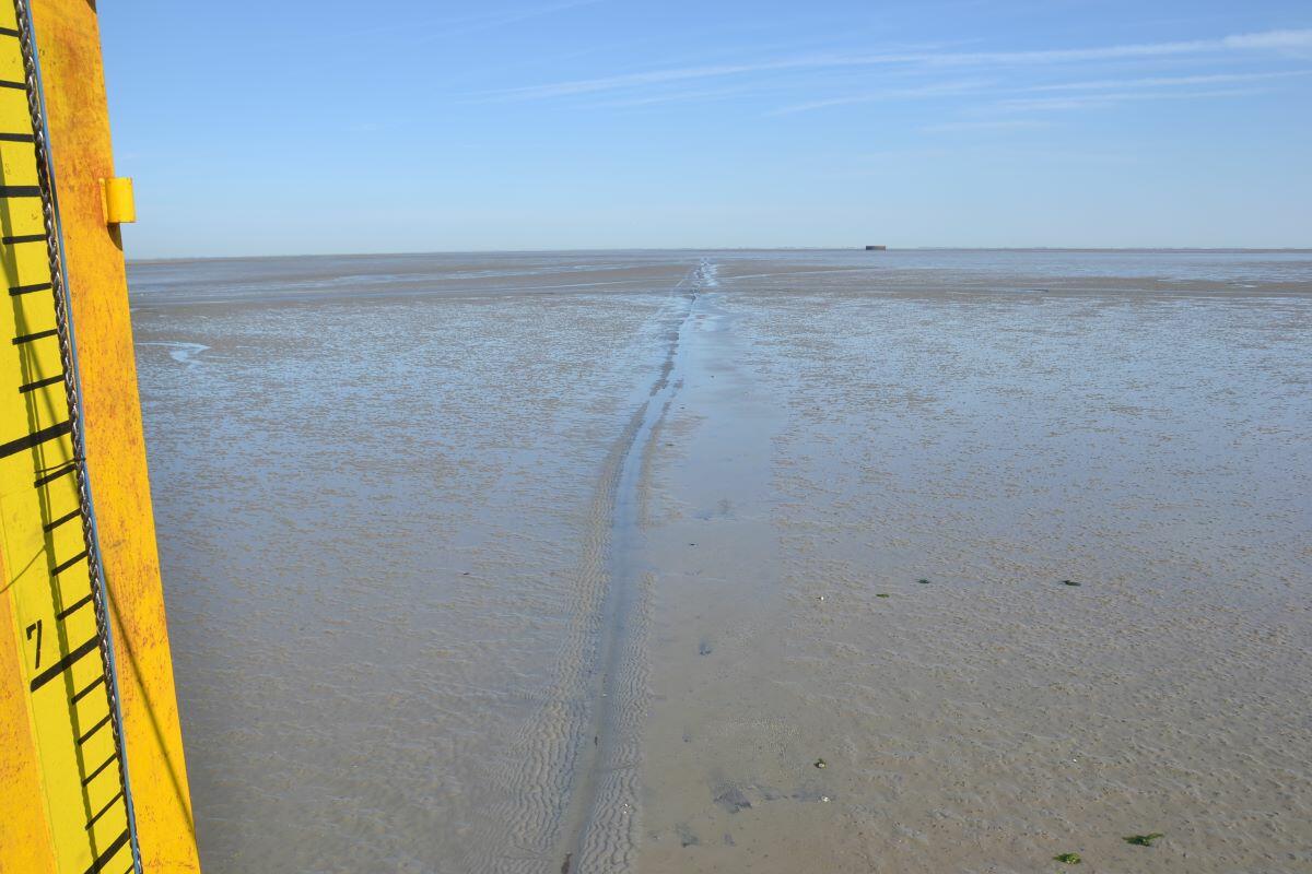 Figure 14. Cable trench a few hours after cable laying with the vibrating plough attached to a barge (Source: HW. Linders).
Moulding cutter
Moulding cutters cut into the sediment and are appropriate for cohesive or hard sediments in the intertidal and subtidal areas. The cutting head digs into the trench and ejects the sediment to both sides. Simultaneously the cable is brought down to laying depth with a cable duct. At water-covered tidal flats, the sediment liquefies during this procedure and a cable trench of about 2.5 m is produced with lateral sediment deposition (Figure 15). This trench does not refill immediately and remains even after several tides. An excavator is needed to refill the trench after cable laying, which leads to further impacts on the sediment.
 Figure 15. Cable laying with a moulding cutter. The remaining trench has to be refilled with an excavator (2008, Hilgenried/Norderney). Source: HW. Linders
Jetting systems
Jetting systems are appropriate for all soft sediments. All jetting systems use water injection. Water is pressed with high pressure through rinsing nozzles, which fluidizes the sediment, and the cable is brought down into the opening trench. Jetting sled and vertical injector are the most commonly used systems for the lower subtidal.
Jetting sled
The jetting sled (Figure 16) is pulled by a cable ship, pontoon or barge and cuts a trench into the sediment with the help of water injection. Simultaneously, the cable is laid into the trench. Instead of a sled also a TROV (trenching remotely operated vehicle) can bury the cable. In this case, the cable has to be laid on the seafloor beforehand. The method is normally applied in the subtidal but has been used as well in the Wadden Sea to cross tidal creeks (Figure 17).
 Figure 16. The jetting sled can be installed behind a cable ship and is dragged over the seafloor. The cable is brought underground with the help of a jet stream (Source: Bohlen & Doyen).
 Figure 17. A jetting sled which was used to cross a tidal creek has created a deep trench into the sandflat (2009, Hilgenried/Norderney) (Source: HW. Linders).
Vertical injector
The vertical injector is attached to a cable ship (Figure 18), pontoon or barge and the blade is dragged through the sediment. Water injection is used to fluidize the sediment and the sea cable is brought down into the opening furrow over a cable duct.
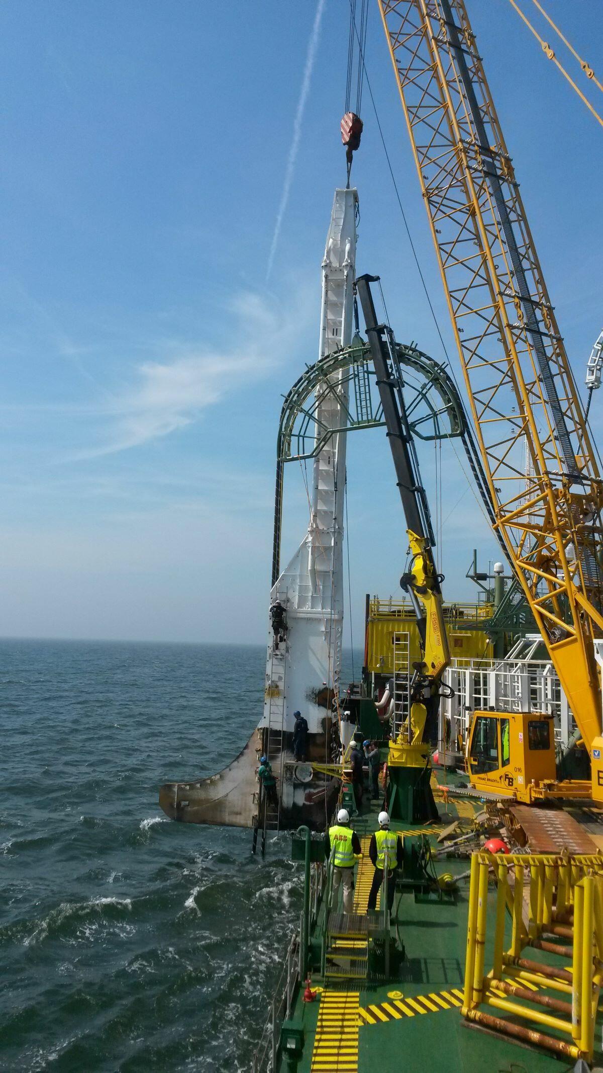 Figure 18. A vertical injector lifted at the stern of a cable ship. Source: Bohlen & Doyen
Positioning of anchors
Barges and pontoons, which are used for shallow water depth, are moved with mooring anchors. Anchors are digging deeply into the sediment and are dragged several metres until they are finally positioned. When the barge or pontoon moves anchoring ropes cause abrasion of the ripple structure. This can also lead to impairment of the epifauna.
Intersections
Intersection buildings are necessary when two cables or pipelines are crossing. Therefore, a concrete mattress is put on the old cable. The new cable is secured with stone rip rap against damage as it cannot be buried at the crossing point.
Sources Table 5
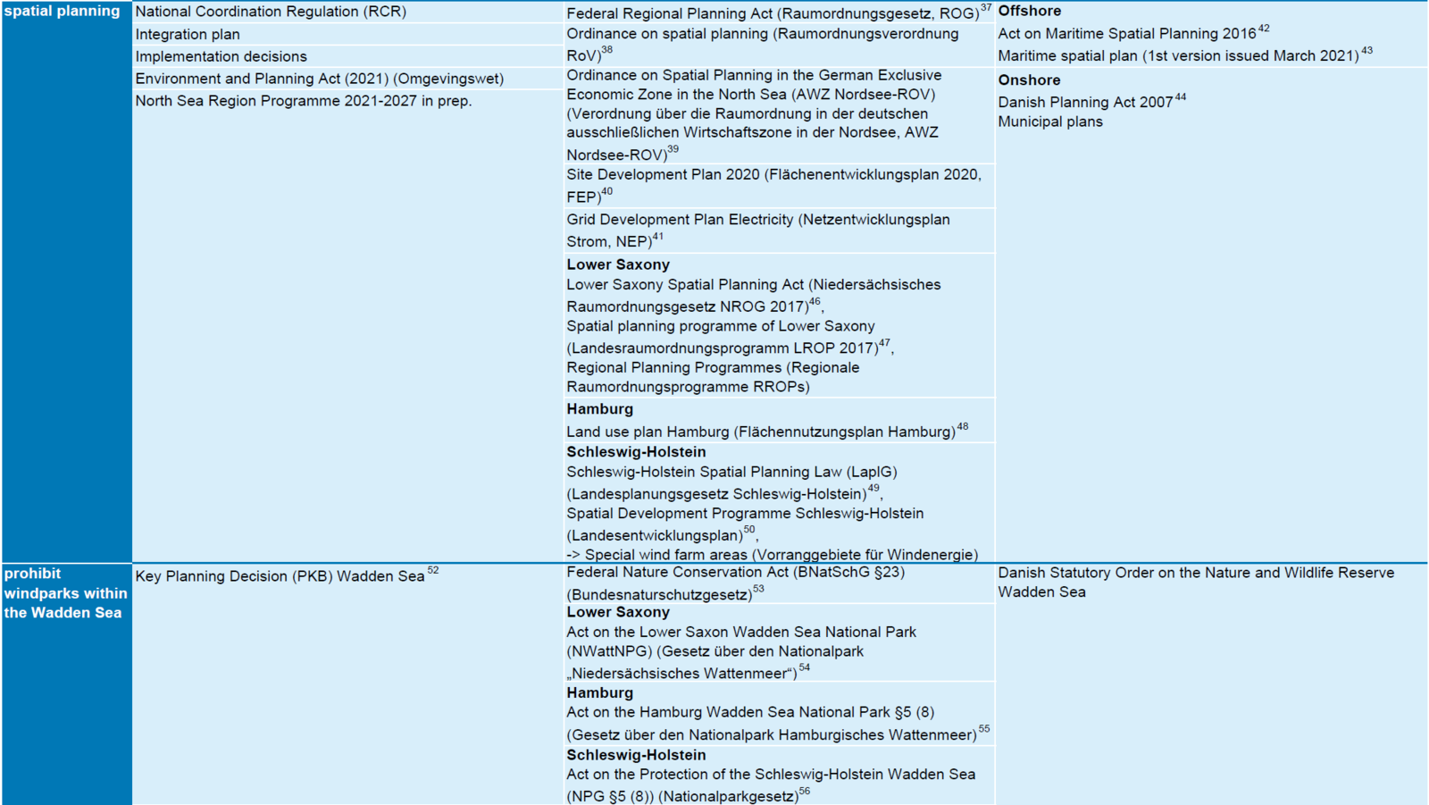
Table 5. International and national legal framework relevant for wind energy (constructions and grid connections) in or adjacent to the Wadden Sea (2021) (Sources: [1] OSPAR Commission, 2008; [2] OSPAR Commission, 2012; [3] OSPAR Commission, 2021; [4] EU, 2008; [5] EU, 2000; [6] EU, 1992; [7] EU, 2009; [8] EU, 2014; [9] UNESCO, 2009; [10] CWSS, 2010; [11] CWSS, 2006; [12] CWSS, 2014; [13] CWSS, 2018; [14] Staatsblad, 2018; [15] Government of the Netherlands, 2013; [16] Noordzeeloket, 2014; [17] Staatsblad, 2015b; [18] RVO, 2018; [19] Staatsblad, 2019; [20] Government of the Netherlands, 2019; [21] Government of the Netherlands, 2022; [22] BZK, 2022; [23] BMU, 2019; [24] BMWK, 2022; [25] BMJ, 2022; [26] BMJ, 2019; [27] KEFM, 2018; [28] KEFM, 2020d; [29] KEFM, 2020e; [30] KEFM, 2020c; [31] KEFM, 2019; [32] KEFM, 2020a; [33] KEFM, 2020b; [34] NI-VORIS, 2020a; [35] Freie und Hansestadt Hamburg, 2019; [36] Landesregierung Schleswig-Holstein, 2021b; [37] BSH, 2021; [38] BMJ, 2020; [39] BMJ, 2021b; [40] BSH, 2020; [41] Netzentwicklungsplan.de, 2021; [42] EM, 2016; [43] Søfartsstyrelsen, 2022; [44] MIM, 2007; [45] Indenrigs og Boligministeriet, 2014; [46] NI-VORIS, 2020b; [47] ML, 2017; [48] Freie und Hansestadt Hamburg, 2013; [49] Landesregierung Schleswig-Holstein, 2014; [50] Landesregierung Schleswig-Holstein, 2021a; [51] Landesregierung Schleswig-Holstein, 2022; [52] VROM, 2007; [53] BMJ, 2009; [54] NI-VORIS, 2001; [55] Freie und Hansestadt Hamburg, 1990; [56] Landesregierung Schleswig-Holstein, 1999).